The XOR or Exclusive OR Gate is a special type of logic gate used in digital electronics to perform the exclusive OR operation. This gate takes two inputs and produces an output depending on the combination of the two inputs applied. This logic gate produces a high or logic 1 output when both of the inputs are dissimilar, otherwise, it produces a logic 0 output.
Operation of XOR Gate
We can explain the operation of the XOR gate as follows:
Returns 1, if the number of logical high input is odd.
Returns 0, if number of logical high input is even.
Say we have two inputs, A and B and the output is called X, then the expression is:
The Boolean expression of XOR Gate is as follows:
X = A'B + AB'
Symbol of XOR Gate
The logic symbol of XOR gate is shown in the following figure. In this figure, the variables A and B represent the input lines and A'B + AB' is the output of the XOR gate.
 Symbol of XOR Gate
Truth Table of XOR Gate
The truth table of an XOR gate is given below. This table shows the relationship between inputs and output of the XOR gate. This also provides information about the operation of XOR gate for different input combinations.
 Truth Table of XOR Gate
Construction of XOR Gate Using Transistor
We can implement exclusive OR gate using transistor. Here is the circuit showing the connection of different circuit elements that are combined to implement the XOR operation.
.png) XOR Gate using NPN Transistor
XOR Gate using NPN TransistorWorking of the Circuit
We will understand this circuit with the help of different scenarios of input in case of 2 input XOR gate:
When both the inputs A and B are zero then transistors Q1,Q2,Q4 and Q5 are open circuit so the LED will not glow because both Q4 and Q5 are open so the negative pin of LED is not connected to the ground.
In this case we can easily see that Q4 is working as close circuit now. So the negative pin of the LED is connected to Q3 via Q4 and ultimately which is connected to ground so in this case LED will glow.
In this case we can easily see that Q5 is working as close circuit now. So the negative pin of the LED is connected to Q3 via Q5 and ultimately which is connected to ground so in this case LED will glow.
In this case when both A and B are logical high then transistor Q1 and Q2 are also activated then the current will directly go from +5V junction to ground through Q1 and Q2 transistors, and will not got in the path where Q3 is connected as a result transistor Q3 will now act as open circuit and ultimately negative pin of LED is disconnected from ground so the LED will not glow.
XOR GATE Implementation using NAND GATE
Expression of XOR gate: A'.B + A.B'
To Convert the expression into NAND form perform the following:
Apply double complement: [(A’.B + A.B’)’]’
Operate internal complement: [ (A’.B)’ . (A.B’)’ ]’
Now, expression is obtained in NAND form.
Pass Input A through the first NAND Gate to get A’, now pass this A’ and B through the second NAND Gate to get (A’.B)’. Similarly, pass Input B through the third NAND Gate to get B’, now pass this B’ and A through the fourth NAND Gate to get (A.B’)’. Pass both the output (A’.B)’ and (A.B’)’ through the fifth NAND Gate to get our desired expression of XOR Gate ((A’.B)’.(A.B’)’)’ = A’B + AB’ (By De-Morgans Law).
Logic diagram
The Logical Diagram of the Following Expression is shown below
 XOR Gate from NAND Gate
XOR GATE Implementation using NOR GATE
To implement XOR gate from NOR gate we follow below steps
- First, we connect both the inputs in NOR gate resulting in (A + B)’.
- Then, after we have another two NOR gates with the inputs A, (A + B)’ and B, (A + B)’ respectively with outputs [A + (A + B)’]’ and [B + (A + B)’]’.
- Again, the connect outputs of the above NOR gates to next NOR gate resulting in the output [A’B + AB’]’.
- Now, the result is generated in complement form so, we connect the result as the input for last NOR gate which gives the output [AB’ + A’B].
- The resultant of the last NOR gate gives us XOR gate.
- So, the number of NOR gates required to implement XOR gate is 5.
below is the logic diagram for implementation of XOR gate from NOR gate:
 Implementation of XOR Gate using NOR Gate
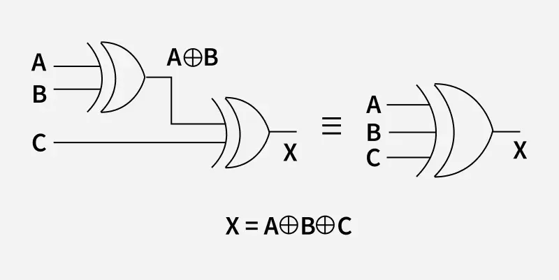
It's important to understand that there isn't a XOR gate with more than two input lines. XOR gates are typically designed with only two inputs. However, if we need an XOR gate with more than two inputs, we can create one by combining multiple two-input XOR gates. By connecting them in a specific way, we can achieve the functionality of an XOR gate with more inputs.
The logic circuit diagram of the 3-Input XOR gate is shown in the following figure. It has three input line denoted by the letter A,B,C and one output line denoted by the letter X where X=A⊕B⊕C. It can be obtained by using two 2-input XOR gates. First, perform the XOR operation on any two of the inputs. Then, XOR the result of that operation with the third input using the second XOR gate.
 3- Input XOR Gate
The Boolean expression of N input XOR Gate is as follows:
Say we have N inputs, A0,A1,...,AN and the output is called X, the expression is:
X=A0⊕A1⊕....⊕AN
The truth table of three input XOR gate is given below:
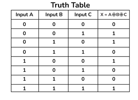 Truth Table of 3-Input XOR Gate
This table shows the relationship between three inputs and one output of the XOR gate. This also provides information about the operation of XOR gate for different input combinations.
Say we have three inputs A,B and C and the output is called X, then the expression is:
X = A⊕B⊕C
Applications of XOR Gate
Here are some of the applications of the XOR Gate:
- Data Encryption: XOR gates are used in data encryption algorithms. As it is used to combine data with secret key to scramble it making it very difficult for unauthorized people to crack.
- Comparator Circuits: It is used in comparator circuit to check if the two binary values are equal or not. As for same type of both the input it gives output 0 and for different inputs it gives output 1.
- Binary addition and subtraction: It helps in determining sum of each bit and also combine with other logic gates to handle borrow operations.
- Toggle Flip flops: In T flip flops it is used to the circuit that toggles with each clock pulse passed.
Some other uses of XOR gates are in Address decoding, Security and access control, Random number generation, clock synchronization, frequency divider circuits etc.
Advantages of XOR Gate
- It helps to detect if there are odd number of '1' in the sequence of inputs.
- XOR gates perform the exclusive OR operation, which is a fundamental operation in digital logic.
Disadvantages of XOR Gate
- XOR gate are complex gate circuit and upon connecting it to the circuit of our use, it causes increased power consumption and circuit complexity.
- It leads to increase in the propagation delay of the circuit.
- Upon increasing the number of inputs the circuit becomes more and more complex making it hard to maintain and detect errors.
Solved Example of XOR Gate
Find a single number from a series of numbers given that every element appears twice except for that one single element.
Solution: We know that XOR of two same bits gives '0' so here we can observe that if we XOR the elements then every elements which are occurring twice will become '0' and only remaining element would be our answer.
Like out of [7,2,2,3,3,4,4,5,5,6,6]
If we XOR each of the above elements then elements occurring even number of times will give '0' and elements occurring odd number of times will give the output. Ultimately we will get 7 as output as only this element is occurring once only and rest other elements are occurring even number of times.