Package Diagram – Unified Modeling Language (UML)
Last Updated : 17 Oct, 2024
A package diagram is a type of structural diagram in UML (Unified Modeling Language) that organizes and groups related classes and components into packages. It visually represents the dependencies and relationships between these packages, helping to illustrate how different parts of a system interact with each other.

A package is used as a container to organize the elements present in the system into a more manageable unit. It is very useful to represent the system's architecture and design as a cohesive unit and a concise manner.
Basic Elements of Package Diagrams
The following are the basic elements of a Package Diagrams:
In a package diagram, several key elements help organize and clarify the relationships within a system:
- Package: This is the fundamental unit of a package diagram, serving as a container for various elements like classes and interfaces. It’s depicted as a folder-like icon with a name label, making it easy to identify.
- NameSpace: This denotes the name of the package and usually appears at the top of the package symbol. It helps uniquely identify the package within the diagram.
- Package Merge: This relationship illustrates how one package can be merged with another. It’s represented by a direct arrow between the two packages, indicating that their contents can combine.
- Package Import: This relationship shows that one package can access the contents of another package, depicted with a dashed arrow.
- Dependency: Dependencies indicate that changes in one package may affect another. This relationship signifies that one element or package relies on another, highlighting how interconnected they are.
- Element: An element is a single unit within a package, which can be a class, interface, or subsystem. Elements reside inside packages and are connected to the main package. For instance, a class may contain various functions and variables, all of which are considered elements tied to that class.
- Constraint: This represents a condition or requirement associated with a package, typically shown in curly braces. Constraints help define the rules or limitations for how the package operates.
Package Structure and Notation
Below are the package structures and their notations:
1. Package
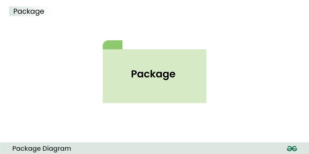
The above is the notation of a simple Package.
2. Subsystem

The above notation is used to represent subsystem.
3. Dependency

The above dashed arrow sign is used to show the dependency among two elements or two packages.
4. Import

The above notation is of the Import, here it also uses a dashed arrow line but the difference is, the word <<import>> is being written to represent the below package or function or element has been imported from the above package.
5. Merge

This notation above denotes that the Package 1 can be merged with Package 2
Package Relationships
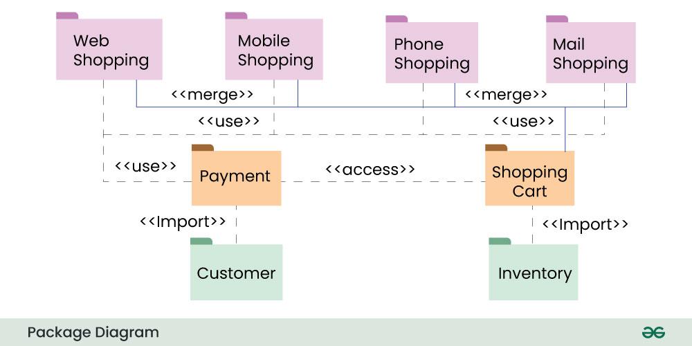
1. Package Merge Relationship
This relationship is used to represent that the contents of a package can be merged with the contents of another package. This implies that the source and the target package has some elements common in them, so that they can be merged together.
Example:

The above diagram depicts that the packages are of different type of payments, but all of them are a some kind of payment mechanism, so they can all be merged to be called as payment.
2. Package Dependency Relationship
A package can be dependant on other different packages, signifying that the source package is somehow dependent on the target package.
Example:
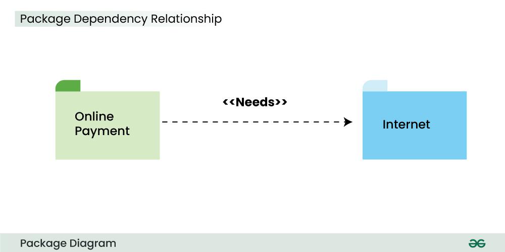
The above diagram depicts that the online payment package is dependent on the Internet package and uses "need" dependency.
3. Package Import Relationship
This relationship is used to represent that a package is importing another package to use. It signifies that the importing package can access the public contents of the imported package.
Example:
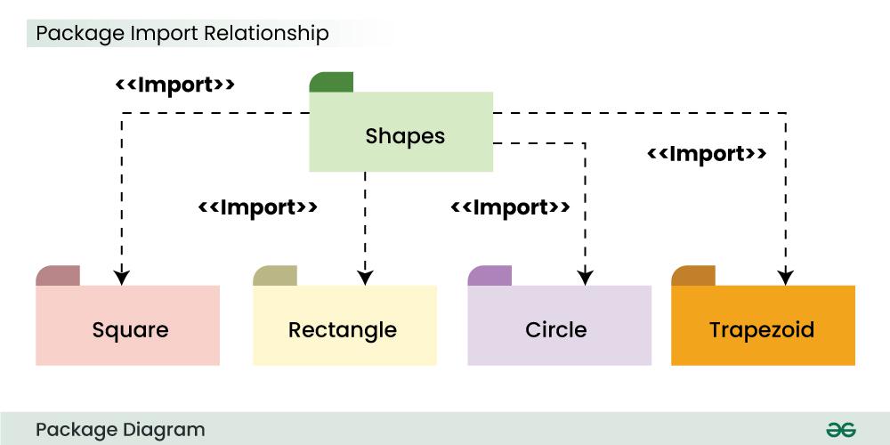
The above package diagram shows the import relationship between the main package Shapes and it's various other sub packages Square, Rectangle etc. They all are importing the real Shapes package so that the public contents of the Shapes package can be used by them.
4. Package Access Relationship
This type of relationship signifies that there is a access relationship between two or more packages, meaning that one package can access the contents of another package without importing it.
Example:
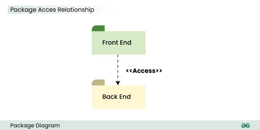
The above diagram depicts the Access relationship between the Front End and Back End services. It is much needed that a front end service can easily access the important Back End services to carry out any operation.
Use Cases of Package Diagrams
A package diagram is a vital tool in system design, helping to model and illustrate the structure of an organization or system. Here are some key use cases:
- It visually represents the system’s structure, organizing elements into smaller, manageable packages. This makes it easier to understand the overall layout.
- The diagram helps manage and organize related modules or components within a system, grouping them for clarity.
- Developers use package diagrams to show dependencies between different packages, which helps clarify the system's architecture and the potential impact of changes.
- System architects can break down complex problems into smaller, manageable parts early in the design process, simplifying component design and implementation.
Best Practices for Package Diagrams
Below are some of the best practices to be followed in case of a Package Diagram:
- It is always recommended to clearly define the package names in such a manner that there is no duplicate present in the same package which might create confusion.
- Organize the packages in a hierarchical manner so that it represents the proper structure of the system and the relationship of the various parts of the system.
- Make the packages concise, use a single package to represent a single function or element. Don't use overcomplicated and complex packages.
- Clearly mention and document the dependencies between the packages using the suitable symbols .This includes dependencies such as associations, generalizations, or dependencies.
Benefits of Package Diagram
Below are the benefits of package diagram:
- It provides a visual representation of the system's architecture, showing that how each elements are organized and interact with each other.
- Package Diagram encourages a modular approach to represent any system in form of smaller and easy to understand packages. It also supports the encapsulation of elements into packages which share a same trait.
- It servers as a common language of commmunication between the developers and the stakeholders.
- By showing the dependency between the different packages, it become easy to identify and manage dependencies between the packages, also it becomes easy to address issues related to coupling and cohesion.
Challenges of Package Diagrams
Below are the challenges of Package diagrams:
- Balancing detail and simplicity in a package diagram is challenging.
- Each package should avoid being overloaded with information to maintain clarity.
- The focus is primarily on the static structure of system elements.
- Package diagrams may not effectively capture dynamic aspects, like runtime behaviors or interactions.
- Dependencies among packages are essential to show, but overemphasis can create clutter.
- Dependencies should be presented clearly and concisely for better understanding.
Package Diagrams in Software Development
Package Diagram plays a significant role in the field of Software Development as a visual representation of an architecture of a system. It helps in understanding , organizing and communication of the structural component of a system.
- Package Diagram provides a high level view of the system's architecture by grouping related elements together to form packages, and representing the dependencies and interactions with each other.
- Package Diagram promotes modularity and encapsulation, which allows the developers to create software with clear boundaries among its components.
- By visually representing classes, interfaces, functions and other elements in a concise manner by including them in a package, software developers can manage the complexity of large software/systems.
Some of the renowned tools and software used to create package diagrams are listed below -
- Enterprise Architect
- Lucidchart
- Visual Paradigm
- Draw.io
- IBM Rhapsody
- PlantUML
- StarUML
- Creately
- Microsoft Visio
Similar Reads
What are UML Diagrams
Unified Modeling Language (UML) Diagrams Unified Modeling Language (UML) is a general-purpose modeling language. The main aim of UML is to define a standard way to visualize the way a system has been designed. It is quite similar to blueprints used in other fields of engineering. UML is not a programming language, it is rather a visual lan
14 min read
UML Full Form The full form of UML is "Unified Modeling Language". It is a general-purpose modeling language. The main aim of UML is to define a standard way to visualize how a system has been designed. It is quite similar to blueprints used in other fields of engineering. UML is not a programming language, it is
3 min read
Structural Diagrams
Class Diagram | Unified Modeling Language (UML) A UML class diagram is a visual tool that represents the structure of a system by showing its classes, attributes, methods, and the relationships between them. It helps everyone involved in a project—like developers and designers—understand how the system is organized and how its components interact
12 min read
Object Diagrams | Unified Modeling Language (UML) Object diagrams are a visual representation in UML (Unified Modeling Language) that illustrates the instances of classes and their relationships within a system at a specific point in time. They display objects, their attributes, and the links between them, providing a snapshot of the system's struc
8 min read
Deployment Diagram in Unified Modeling Language(UML) A Deployment Diagram is a type of Structural UML Diagram that shows the physical deployment of software components on hardware nodes. It illustrates the mapping of software components onto the physical resources of a system, such as servers, processors, storage devices, and network infrastructure.Ta
8 min read
Package Diagram – Unified Modeling Language (UML) A package diagram is a type of structural diagram in UML (Unified Modeling Language) that organizes and groups related classes and components into packages. It visually represents the dependencies and relationships between these packages, helping to illustrate how different parts of a system interac
7 min read
Behavioral Diagrams
Behavioral Diagrams | Unified Modeling Language(UML) Complex applications need collaboration and planning from multiple teams and hence require a clear and concise way to communicate amongst them. So UML becomes essential to communicate with non-programmers about essential requirements, functionalities, and processes of the system. UML is linked with
7 min read