Half Adder and Half Subtractor using NAND NOR gates
Last Updated : 14 May, 2025
A Half Adder is a digital circuit that adds two single-bit binary numbers and outputs the sum and carry. It can be implemented using either NAND gates or with NOR gates.
When using NAND gates : The sum output is given by A AND B. The carry output is given by the A AND B.
When NOR gate is used : The sum output is NOR of the inputs A and B. Carry output is OR of the inputs A and B.
Half Subtractor is any electronic system which takes two one-bit binary numbers as inputs and generates the difference along with borrow as output. Besides, they can also be made using NAND or NOR gates.
While applying NAND gates : The Difference output is given by, the NAND for the inputs (A and B). While the borrow output is given by NAND, input A and inverted input B.
Conversely for NOR gates : The difference output has been obtained by NOR operation on (A and B) inputs. While the borrow produces NOT operation on input A and B.
These circuits act as basic blocks in digitization whereas they are very important regarding numerical calculations in computers.
What is Half Adder
A Half Adder is an inverter that takes two binary numbers of single bit and adds them. The two inputs represent the bits inputted for addition while there are two outputs. These outputs indicate a sum bit and carry bit respectively.
Block Diagram of Half Adder
 Block Diagram for Half Adder
Truth Table of Half Adder
A | B | S (Sum) | C (Carry) |
|---|
0 | 0 | 0 | 0 |
0 | 1 | 1 | 0 |
1 | 0 | 1 | 0 |
1 | 1 | 0 | 1 |
What is Half Subtractor
A half subtractor is another digital circuit that is used in binary subtraction. It works on two single-bit binary numbers. It has two inputs and two outputs like the half adder, again. The minuend (i.e., the number from which something is going to be deducted), and the subtrahend (the number that this something will represent), form the inputs. On the other hand, the outputs include a difference bit and a borrow bit.
Block Diagram of Half Subtractor
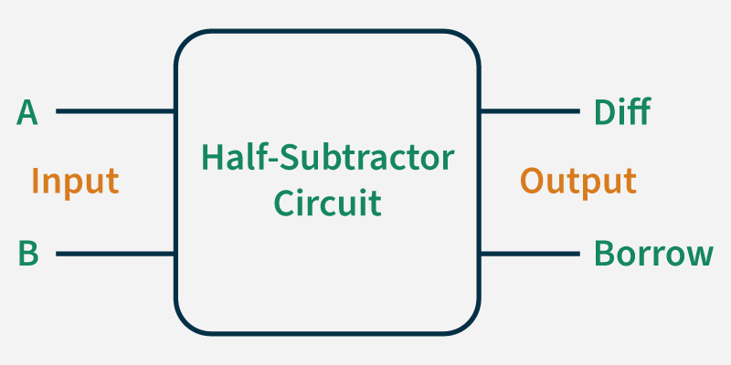 Block Diagram for Half Subtractor
 Truth Table of Half Subtractor
A | B | Diff | Borrow |
|---|
0 | 0 | 0 | 0 |
0 | 1 | 1 | 1 |
1 | 0 | 1 | 0 |
1 | 1 | 0 | 0 |
Implementation
Implementation of Half Adder using NAND gates:
Total 5 NAND gates are required to Implement Half Adder Implementation of Half Adder using NOR gates:
Total 5 NOR gates are required to implement Half Adder  Implementation of Half Subtractor using NAND gates:
Total 5 NAND gates are required to Implement Half Subtractor Implementation of Half Subtractor using NOR gates:
Total 5 NOR gates are required to Implement Half Subtractor
Advantages of Using NAND and NOR Gates to Implement Half Adder and Half Subtractor
- Universality: NAND and NOR gates are considered universal gates because they can be used to implement any logical function, including binary arithmetic functions such as addition and subtraction.
- Cost-effectiveness: NAND and NOR gates are relatively simple and inexpensive to manufacture compared to other types of gates.
- Reduced power consumption: NAND and NOR gates consume less power compared to other types of gates, making them suitable for low-power applications.
Disadvantages of Using NAND and NOR Gates to Implement Half Adder and Half Subtractor
- Propagation delay: The propagation delay of NAND and NOR gates can be higher compared to other types of gates, which can affect the overall performance of the system.
- Noise susceptibility: NAND and NOR gates can be susceptible to noise and other types of interference, which can cause incorrect operation of the circuit.
- In conclusion, while NAND and NOR gates have their advantages, they are not suitable for all applications. The choice of gates depends on the specific requirements of the circuit and the design trade-offs between performance, cost, and power consumption.
Similar Reads
Representation of Boolean Functions Boolean functions are expressions involving Boolean variables and operators, such as AND, OR, and NOT. These functions are fundamental in digital logic design, computer science, and engineering.Table of ContentWhat are Boolean Functions?Definition of Boolean FunctionsRepresentation of Boolean Functi
10 min read
Canonical and Standard Form Canonical Form - In Boolean algebra, the Boolean function can be expressed as Canonical Disjunctive Normal Form known as minterm and some are expressed as Canonical Conjunctive Normal Form known as maxterm. In Minterm, we look for the functions where the output results in "1" while in Maxterm we loo
6 min read
Functional Completeness in Digital Logic Functional Completeness is a crucial concept in digital logic design. A set of logical operators is functionally complete if it can be used to express any Boolean function. This means that any logical operation, regardless of complexity, can be constructed using only operators from a functionally co
6 min read
Introduction of K-Map (Karnaugh Map) In many digital circuits and practical problems, we need to find expressions with minimum variables. We can minimize Boolean expressions of 3, 4 variables very easily using K-map without using any Boolean algebra theorems. It is a tool which is used in digital logic to simplify boolean expression. I
5 min read
Various Implicants in K-Map An implicant can be defined as a product/minterm term in Sum of Products (SOP) or sum/maxterm term in Product of Sums (POS) of a Boolean function. For example, consider a Boolean function, F = AB + ABC + BC. Implicants are AB, ABC, and BC. There are various implicant in K-Map listed below :Prime Imp
5 min read
PDNF and PCNF in Discrete Mathematics PDNF (Principal Disjunctive Normal Form)It stands for Principal Disjunctive Normal Form. It refers to the Sum of Products, i.e., SOP. For eg. : If P, Q, and R are the variables then (P. Q'. R) + (P' . Q . R) + (P . Q . R') is an example of an expression in PDNF. Here '+' i.e. sum is the main operato
4 min read
Variable Entrant Map (VEM) in Digital Logic K-map is the best manual technique to solve Boolean equations but it becomes difficult to manage when number of variables exceed 5 or 6. So, a technique called Variable Entrant Map (VEM) is used to increase the effective size of k-map. It allows a smaller map to handle large number of variables. Thi
3 min read
Consensus Theorem in Digital Logic The Consensus Theorem is a simplification rule in Boolean algebra that helps in minimizing logical expressions by eliminating redundant terms. That is why it is also known as Redundancy Theorem. To apply this theorem, the Boolean expression must meet following conditions:The expression should consis
5 min read
Difference between Combinational and Sequential Circuit In digital electronics, circuits are classified into two primary categories: The combinational circuits and the sequential circuits. Where the outputs depend on the current inputs are called combination circuit, combinational circuits are simple and effective for functions like addition, subtraction
4 min read
Half Adder in Digital Logic A half adder is a combinational logic circuit that performs binary addition of two single-bit inputs, A and B, producing two outputs: SUM and CARRY. The SUM output which is the least significant bit (LSB) is obtained using an XOR gate while the CARRY output which is the most significant bit (MSB) is
3 min read