Realization of Logic Gate Using Universal gates
Last Updated : 09 Apr, 2025
In Boolean Algebra, the NAND and NOR gates are called universal gates because any digital circuit can be implemented by using any one of these two i.e. any logic gate can be created using NAND or NOR gates only.
Implementation of AND Gate using Universal Gates
Implementation using NAND Gates
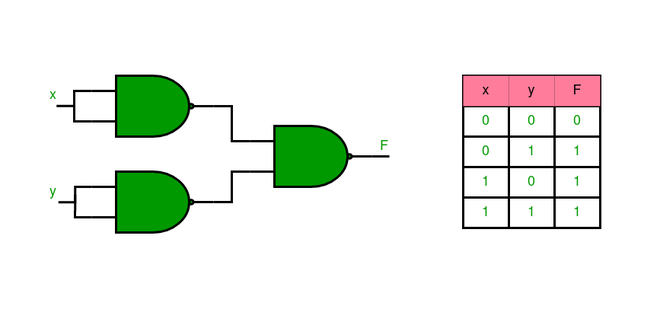
The AND gate is implemented using two NAND gates where the output is HIGH only when both inputs are HIGH. The first NAND gate performs a standard NAND functions, the second NAND gate has both inputs tied to the output of the initial NAND gate as shown below. This particular configuration flips the output thus emulating the behavior of an AND gate.
The AND gate can be implemented by using two NAND gates in the below fashion:

Implementation using NOR Gates
AND gate is implemented using three NOR gates and the setting of this Gate is referred to as 111. The inputs are then transformed with the use of a NOR gate and then they are negated one more time by using two more NOR gates. Together, these create the AND function, meaning that all of the conditions set have to be met in order to pass.
Implementation of AND gate using only NOR gates as shown below

Implementation of OR Gate using Universal Gates
Implementation Using NAND Gates
It is implemented using three NAND gates. The inputs are first inverted using two NAND gates having their inputs probed in parallel and then the inverted outputs are connected with the input of third NAND gate. The last NAND gate effectively performs the inverted signals to give the required OR gate function.
The OR gate can be implemented using the NAND gate as below
Implementation using NOR Gates
The OR gate is created by using an inverse of the output of the NOR operation. An inverted form of the inputs is provided directly into the NOR gate while the output is provided in NOR gate using fixed inputs. This inversion gives the OR gate logic as shown below.
Implementation of OR gate using two NOR gates as shown in the picture below:

Implementation of NOT Gate using Universal gates.
Implementation using NAND Gates
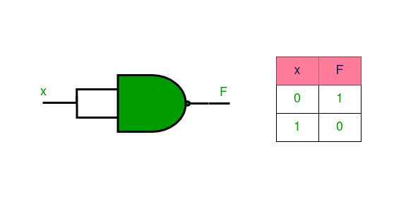
A single NAND gate with ‘a’ and ‘b’ inputs connected respond to a NOT gate. The NOT gate function is achieved as the result of NAND operation because the input signal is inverted.
Implementation of NOT gate using a single NAND gate as shown in the picture below:
Implementation Using NOR Gates
A single NOR gate with joining of both inputs perform the function of NOT gate. The input is negated and the output thus obtained is the inversion that is characteristic of an NOT gate.
Implementation of NOT gate using a single NOR gate as shown in the picture below:

Implementation of XOR Gate using Universal gates.
Implementation using NAND Gates
XOR gate can be implemented using four NAND gates as illustrated below. The circuit first detects differences between inputs and processes them to produce the XOR function.
Implementation of XOR gate using four NAND gate as shown in the picture below

Implementation Using NOR Gates
The XOR gate is implemented by five gates and these gates are the NOR gates. The inputs are then passed through a number of NOR gates to remove all the non-exclusive conditions before the XOR is applied to them.
Implementation of XOR gate using five NOR gate as shown in the picture below:

Implementation of XNOR Gate using Universal Gates
Implementation Using NAND Gate
XNOR gate is implemented by five NAND gates to make the circuit. The XOR logic is first obtained, and then the outgoing XOR signal is passed through a NAND gate that negates it to obtain the XNOR function.
Implementation of XNOR gate using five NAND gate as shown in the picture below:

Implementation Using NOR Gate
The XNOR gate can be implemented using four NOR gates. The XOR logic is then allowed to pass through a NOR gate, and the logic of output obtained will be the XNOR.
Implementation of XNOR gate using four NOR gate as shown in the picture below:

Implementation of NOR Gate using NAND Gates
NOR gate is formed by using four NAND gates. The first two gates perform the operation of inversion of inputs while the subsequent two gates perform the normal NOR operation.
Implementation of NOR gate using four NAND gate as shown in the picture below:

Implementation of NAND Gate using NOR Gates
The NAND gate is made using four NOR gates. The first two gates invert the inputs, and next two gates perform the operations equivalent to NAND operation by these inverted signals.
Implementation of NAND gate using four NOR gate as shown in the picture below

Advantages of Using Universal Gates
- Simplicity: These are gates that can be used for all forms of logical operations hence can help reduce the number of components in a circuit.
- Cost-Effective: Fewer parts are required when developing one type of gate only thus lowering costs of manufacturing.
- Flexibility:Universal gates can perform any digital logic function which makes it convenient to design any type of circuit.
- Reliability: The dependence of a small number of various gates can result in increased reliability in digital circuits.
- Ease of Integration: Universal gates can be easily integrated into existing systems, even for complex designs.
Disadvantages of Using Universal Gates
- Increased Gate Count: Complex logic functions are more difficult to construct using only NAND or NOR gates in that they take up more gates than other basic gates.
- Higher Power Consumption: Additional gates increase power consumption, especially in complex circuits.
- Slower Speed: Extra gates can also bring in more propagation delay, and hence lower the speed of the circuit.
- Complex Design: The circuit design becomes more complicated because of a high number of universal gates the functions contain.
- Limited Optimization: The use of only one type of gate may offer fewer optimization possibilities and therefore result in less efficient designs.
Applications of Universal Gates
- Basic Digital Circuits: Universal gates are employed widely in elementary digital circuits for carrying out simple logical operations.
- Memory Units: NAND and NOR gates are used in memory storage elements such as SRAM and DRAM among others in the manufacture of devices that are used in the modern world.
- Arithmetic Logic Units (ALUs): The universal gates are used in ALUs to transform constant and variable, arithmetic and logical operations with the aid of processors.
- Signal Processing: In filter design and other communication processing systems popularly known as modulation techniques, universal gates are employed.
- Embedded Systems: Universal gates play a significant role in the construction of small scale circuits to be used in the embedded systems applications.
Similar Reads
Digital Electronics and Logic Design Tutorials Digital Electronics and Logic Design are key concepts in both electronics and computer science. Digital systems are at the core of everything from basic devices like calculators to advanced computing systems. Digital systems use binary numbers (0s and 1s) to represent and process information.Logic g
4 min read
Number Systems
Boolean Algebra and Logic Gates
Logic Gates - Definition, Types, UsesLogic Gates are the fundamental building blocks in digital electronics. There are basically seven main types of logic gates that are used to perform various logical operations in digital systems. By combining different logic gates, complex operations are performed, and circuits like flip-flops, coun
10 min read
Basic Conversion of Logic GatesIn the Digital System, logic gates are the basic building blocks. Â In these logic gates, we can find the gates having more than one input, but will have only one output. The connection between the input and the output of a gate is based on some logic. Based on this logic, different gates are develop
6 min read
Realization of Logic Gate Using Universal gatesIn Boolean Algebra, the NAND and NOR gates are called universal gates because any digital circuit can be implemented by using any one of these two i.e. any logic gate can be created using NAND or NOR gates only.Implementation of AND Gate using Universal GatesImplementation using NAND GatesThe AND ga
6 min read
Canonical and Standard FormCanonical Form - In Boolean algebra, the Boolean function can be expressed as Canonical Disjunctive Normal Form known as minterm and some are expressed as Canonical Conjunctive Normal Form known as maxterm. In Minterm, we look for the functions where the output results in "1" while in Maxterm we loo
6 min read
Types of Integrated CircuitsIn this article, we will go through the Types of Integrated Circuits, we will start our article with the introductions of the ICs, then we will go through different types of ICs one by one, At last, we will conclude our article will their applications, advantages, disadvantages and some FAQs. Table
7 min read
Minimization Techniques
Minimization of Boolean FunctionsBoolean functions are used to represent logical expressions in terms of sum of minterms or product of maxterms. Number of these literals (minterms or maxterms) increases as the complexity of the digital circuit increases. This can lead to large and inefficient circuits. By minimizing Boolean functio
4 min read
Introduction of K-Map (Karnaugh Map)In many digital circuits and practical problems, we need to find expressions with minimum variables. We can minimize Boolean expressions of 3, 4 variables very easily using K-map without using any Boolean algebra theorems. It is a tool which is used in digital logic to simplify boolean expression. I
5 min read
5 variable K-Map in Digital LogicPrerequisite - Implicant in K-Map Karnaugh Map or K-Map is an alternative way to write a truth table and is used for the simplification of Boolean Expressions. So far we are familiar with 3 variable K-Map & 4 variable K-Map. Now, let us discuss the 5-variable K-Map in detail. Any Boolean Express
5 min read
Various Implicants in K-MapAn implicant can be defined as a product/minterm term in Sum of Products (SOP) or sum/maxterm term in Product of Sums (POS) of a Boolean function. For example, consider a Boolean function, F = AB + ABC + BC. Implicants are AB, ABC, and BC. There are various implicant in K-Map listed below :Prime Imp
5 min read
Don't Care (X) Conditions in K-MapsOne of the most important concepts in simplifying output expressions using Karnaugh Maps (K-Maps) is the 'Don't Care' condition. The 'Don't Care' conditions allow us to treat certain cells in a K-Map as either 0, 1, or to ignore them altogether, which can help in forming larger and more efficient gr
4 min read
Quine McCluskey MethodThe Quine McCluskey method also called the tabulation method is a very useful and convenient method for simplification of the Boolean functions for a large number of variables (greater than 4). This method is useful over K-map when the number of variables is larger for which K-map formation is diffi
8 min read
Two Level Implementation of Logic GatesThe term "two-level logic" refers to a logic design that uses no more than two logic gates between input and output. This does not mean that the entire design will only have two logic gates, but it does mean that the single path from input to output will only have two logic gates.In two-level logic,
9 min read
Combinational Circuits
Half Adder in Digital LogicA half adder is a combinational logic circuit that performs binary addition of two single-bit inputs, A and B, producing two outputs: SUM and CARRY. The SUM output which is the least significant bit (LSB) is obtained using an XOR gate while the CARRY output which is the most significant bit (MSB) is
3 min read
Full Adder in Digital LogicFull Adder is a combinational circuit that adds three inputs and produces two outputs. The first two inputs are A and B and the third input is an input carry as C-IN. The output carry is designated as C-OUT and the normal output is designated as S which is SUM. The C-OUT is also known as the majorit
5 min read
Half Subtractor in Digital LogicA half subtractor is a digital logic circuit that performs the binary subtraction of two single-bit binary numbers. It has two inputs, A and B, and two outputs, Difference and Borrow. The Difference output represents the result of subtracting B from A, while the Borrow output indicates whether a bor
4 min read
Full Subtractor in Digital LogicA Full Subtractor is a combinational circuit used to perform binary subtraction. It has three inputs:A (Minuend)B (Subtrahend)B-IN (Borrow-in from the previous stage)It produces two outputs:Difference (D): The result of the subtraction.Borrow-out (B-OUT): Indicates if a borrow is needed for the next
3 min read
Parallel Adder and Parallel SubtractorAn adder adds two binary numbers one bit at a time using carry from each step. A subtractor subtracts one binary number from another using borrow when needed. A parallel adder adds all bits at once, making addition faster. Similarly, a parallel subtractor subtracts all bits at the same time for quic
5 min read
Sequential Binary MultiplierIn this article, we are going to learn how a sequential binary multiplier works with examples. So for that, we also need to learn a few concepts related to the sequential circuit, binary multipliers, etc. Finally solving the examples using a sequential binary multiplier method.Sequential CircuitA se
12 min read
Multiplexers in Digital LogicIn this article we will go through the multiplexer, we will first define what is a multiplexer then we will go through its types which are 2x1 and 4x1, then we will go through the Implementation of the 2x1 mux and higher mux with lower order mux, at last we will conclude our article with some applic
10 min read
Event Demultiplexer in Node.jsNode.js is designed to handle multiple tasks efficiently using asynchronous, non-blocking I/O operations. But how does it manage multiple operations without slowing down or blocking execution? The answer lies in the Event Demultiplexer.The Event Demultiplexer is a key component of Node.js's event-dr
3 min read
Binary Decoder in Digital LogicA binary decoder is a digital circuit used to convert binary-coded inputs into a unique set of outputs. It does the opposite of what an encoder does. A decoder takes a binary value (such as 0010) and activates exactly one output line corresponding to that value while all other output lines remain in
5 min read
Encoder in Digital LogicAn encoder is a digital circuit that converts a set of binary inputs into a unique binary code. The binary code represents the position of the input and is used to identify the specific input that is active. Encoders are commonly used in digital systems to convert a parallel set of inputs into a ser
7 min read
Code Converters - Binary to/from Gray CodeIn this article, we will go through Code Converters - Binary to/from Gray Code, we will start our article by defining Code converters, Binary code and Gray code, and then we will go through the conversion of binary code to gray code and vice versa.Table Of ContentCode ConvertersBinary CodeGray CodeC
5 min read
Magnitude Comparator in Digital LogicA magnitude digital Comparator is a combinational circuit that compares two digital or binary numbers in order to find out whether one binary number is equal, less than, or greater than the other binary number. We logically design a circuit for which we will have two inputs one for A and the other f
7 min read
Sequential Circuits
Introduction of Sequential CircuitsSequential circuits are digital circuits that store and use the previous state information to determine their next state. Unlike combinational circuits, which only depend on the current input values to produce outputs, sequential circuits depend on both the current inputs and the previous state stor
7 min read
Difference between Combinational and Sequential CircuitIn digital electronics, circuits are classified into two primary categories: The combinational circuits and the sequential circuits. Where the outputs depend on the current inputs are called combination circuit, combinational circuits are simple and effective for functions like addition, subtraction
4 min read
Latches in Digital LogicLatch is a digital circuit which converts its output according to its inputs instantly. To implement latches, we use different logic gates. In this article, we will see the definition of latches, latch types like SR, gated SR, D, gated D, JK and T with its truth table and diagrams and advantages and
7 min read
Flip-Flop types, their Conversion and ApplicationsIn this article, we will go through the Flip-Flop types, their Conversion and their Applications, First, we will go through the definition of the flip-flop with its types in brief, and then we will go through the conversion of the flip-flop with its applications, At last, we will conclude our articl
7 min read
Conversion of Flip-Flop
Register, Counter, and Memory Unit
Counters in Digital LogicA Counter is a device which stores (and sometimes displays) the number of times a particular event or process has occurred, often in relationship to a clock signal. Counters are used in digital electronics for counting purpose, they can count specific event happening in the circuit. For example, in
4 min read
Ripple Counter in Digital LogicCounters play a crucial role in digital logic circuits, enabling tasks such as clock frequency division and sequencing. This article explores the concept of ripple counters, a type of asynchronous counter, their operation, advantages, and disadvantages in digital logic design. What is a Counter?Coun
5 min read
Ring Counter in Digital LogicA ring counter is a typical application of the Shift register. The ring counter is almost the same as the shift counter. The only change is that the output of the last flip-flop is connected to the input of the first flip-flop in the case of the ring counter but in the case of the shift register it
7 min read
General Purpose RegistersA register is a collection of flip-flops. Single bit digital data is stored using flip-flops. By combining many flip-flops, the storage capacity can be extended to accommodate a huge number of bits. We must utilize an n-bit register with n flip flops if we wish to store an n-bit word.General Purpose
8 min read
Shift Registers in Digital LogicPre-Requisite: Flip-FlopsFlip flops can be used to store a single bit of binary data (1 or 0). However, in order to store multiple bits of data, we need multiple flip-flops. N flip flops are to be connected in order to store n bits of data. A Register is a device that is used to store such informati
8 min read
Computer MemoryComputer memory is just like the human brain. It is used to store data/information, and instructions. It is a data storage unit or a data storage device where data is to be processed, and instructions required for processing are stored. Both the input and output can be stored here.It's faster than s
9 min read
Random Access Memory (RAM)Random Access Memory (RAM) is a type of computer memory that stores data temporarily. When you turn off your computer, the data in RAM disappears, unlike the data on your hard drive, which stays saved. RAM helps your computer run programs and process information faster. This is similar to how the br
11 min read
Read Only Memory (ROM)Memory plays a crucial role in how devices operate, and one of the most important types is Read-Only Memory (ROM). Unlike RAM (Random Access Memory), which loses its data when the power is turned off, ROM is designed to store essential information permanently.Here, we’ll explore what ROM is, how it
8 min read
LMNs and GATE PYQs
Practice Questions - Digital Logic & Design