Encoders and Decoders in Digital Logic
Last Updated : 10 Jul, 2024
Binary code of N digits can be used to store 2N distinct elements of coded information. This is what encoders and decoders are used for.
Encoders convert 2N lines of input into a code of N bits and Decoders decode the N bits into 2N lines.
1. Encoders - An encoder is a combinational circuit that converts binary information in the form of a 2N input lines into N output lines, which represent N bit code for the input. For simple encoders, it is assumed that only one input line is active at a time. As an example, let’s consider Octal to Binary encoder. As shown in the following figure, an octal-to-binary encoder takes 8 input lines and generates 3 output lines.

Truth Table -
| D7 | D6 | D5 | D4 | D3 | D2 | D1 | D0 | X | Y | Z |
|---|
| 0 | 0 | 0 | 0 | 0 | 0 | 0 | 1 | 0 | 0 | 0 |
| 0 | 0 | 0 | 0 | 0 | 0 | 1 | 0 | 0 | 0 | 1 |
| 0 | 0 | 0 | 0 | 0 | 1 | 0 | 0 | 0 | 1 | 0 |
| 0 | 0 | 0 | 0 | 1 | 0 | 0 | 0 | 0 | 1 | 1 |
| 0 | 0 | 0 | 1 | 0 | 0 | 0 | 0 | 1 | 0 | 0 |
| 0 | 0 | 1 | 0 | 0 | 0 | 0 | 0 | 1 | 0 | 1 |
| 0 | 1 | 0 | 0 | 0 | 0 | 0 | 0 | 1 | 1 | 0 |
| 1 | 0 | 0 | 0 | 0 | 0 | 0 | 0 | 1 | 1 | 1 |
As seen from the truth table, the output is 000 when D0 is active; 001 when D1 is active; 010 when D2 is active and so on.
Implementation -
From the truth table, the output line Z is active when the input octal digit is 1, 3, 5 or 7. Similarly, Y is 1 when input octal digit is 2, 3, 6 or 7 and X is 1 for input octal digits 4, 5, 6 or 7. Hence, the Boolean functions would be:
X = D4 + D5 + D6 + D7
Y = D2 +D3 + D6 + D7
Z = D1 + D3 + D5 + D7
Hence, the encoder can be realised with OR gates as follows:

One limitation of this encoder is that only one input can be active at any given time. If more than one inputs are active, then the output is undefined. For example, if D6 and D3 are both active, then, our output would be 111 which is the output for D7. To overcome this, we use Priority Encoders. Another ambiguity arises when all inputs are 0. In this case, encoder outputs 000 which actually is the output for D0 active. In order to avoid this, an extra bit can be added to the output, called the valid bit which is 0 when all inputs are 0 and 1 otherwise.
Priority Encoder -
A priority encoder is an encoder circuit in which inputs are given priorities. When more than one inputs are active at the same time, the input with higher priority takes precedence and the output corresponding to that is generated. Let us consider the 4 to 2 priority encoder as an example. From the truth table, we see that when all inputs are 0, our V bit or the valid bit is zero and outputs are not used. The x’s in the table show the don’t care condition, i.e, it may either be 0 or 1. Here, D3 has highest priority, therefore, whatever be the other inputs, when D3 is high, output has to be 11. And D0 has the lowest priority, therefore the output would be 00 only when D0 is high and the other input lines are low. Similarly, D2 has higher priority over D1 and D0 but lower than D3 therefore the output would be 010 only when D2 is high and D3 are low (D0 & D1 are don’t care).
Truth Table -
| D3 | D2 | D1 | D0 | X | Y | V |
|---|
| 0 | 0 | 0 | 0 | x | x | 0 |
| 0 | 0 | 0 | 1 | 0 | 0 | 1 |
| 0 | 0 | 1 | x | 0 | 1 | 1 |
| 0 | 1 | x | x | 1 | 0 | 1 |
| 1 | x | x | x | 1 | 1 | 1 |
Implementation -
It can clearly be seen that the condition for valid bit to be 1 is that at least any one of the inputs should be high. Hence,
V = D0 + D1 + D2 + D3
For X:

=> X = D2 + D3 For Y:
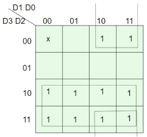
=> Y = D1 D2’ + D3 Hence, the priority 4-to-2 encoder can be realized as follows:

2. Decoders -
A decoder does the opposite job of an encoder. It is a combinational circuit that converts n lines of input into 2
n
lines of output. Let’s take an example of 3-to-8 line decoder.
Truth Table -
| X | Y | Z | D0 | D1 | D2 | D3 | D4 | D5 | D6 | D7 |
|---|
| 0 | 0 | 0 | 1 | 0 | 0 | 0 | 0 | 0 | 0 | 0 |
| 0 | 0 | 1 | 0 | 1 | 0 | 0 | 0 | 0 | 0 | 0 |
| 0 | 1 | 0 | 0 | 0 | 1 | 0 | 0 | 0 | 0 | 0 |
| 0 | 1 | 1 | 0 | 0 | 0 | 1 | 0 | 0 | 0 | 0 |
| 1 | 0 | 0 | 0 | 0 | 0 | 0 | 1 | 0 | 0 | 0 |
| 1 | 0 | 1 | 0 | 0 | 0 | 0 | 0 | 1 | 0 | 0 |
| 1 | 1 | 0 | 0 | 0 | 0 | 0 | 0 | 0 | 1 | 0 |
| 1 | 1 | 1 | 0 | 0 | 0 | 0 | 0 | 0 | 0 | 1 |
Implementation -
D0 is high when X = 0, Y = 0 and Z = 0. Hence,
D0 = X’ Y’ Z’
Similarly,
D1 = X’ Y’ Z
D2 = X’ Y Z’
D3 = X’ Y Z
D4 = X Y’ Z’
D5 = X Y’ Z
D6 = X Y Z’
D7 = X Y Z
Hence,

Similar Reads
Canonical and Standard Form Canonical Form - In Boolean algebra, the Boolean function can be expressed as Canonical Disjunctive Normal Form known as minterm and some are expressed as Canonical Conjunctive Normal Form known as maxterm. In Minterm, we look for the functions where the output results in "1" while in Maxterm we loo
6 min read
Functional Completeness in Digital Logic Functional Completeness is a crucial concept in digital logic design. A set of logical operators is functionally complete if it can be used to express any Boolean function. This means that any logical operation, regardless of complexity, can be constructed using only operators from a functionally co
6 min read
Introduction of K-Map (Karnaugh Map) In many digital circuits and practical problems, we need to find expressions with minimum variables. We can minimize Boolean expressions of 3, 4 variables very easily using K-map without using any Boolean algebra theorems. It is a tool which is used in digital logic to simplify boolean expression. I
5 min read
Various Implicants in K-Map An implicant can be defined as a product/minterm term in Sum of Products (SOP) or sum/maxterm term in Product of Sums (POS) of a Boolean function. For example, consider a Boolean function, F = AB + ABC + BC. Implicants are AB, ABC, and BC. There are various implicant in K-Map listed below :Prime Imp
5 min read
PDNF and PCNF in Discrete Mathematics PDNF (Principal Disjunctive Normal Form)It stands for Principal Disjunctive Normal Form. It refers to the Sum of Products, i.e., SOP. For eg. : If P, Q, and R are the variables then (P. Q'. R) + (P' . Q . R) + (P . Q . R') is an example of an expression in PDNF. Here '+' i.e. sum is the main operato
4 min read
Variable Entrant Map (VEM) in Digital Logic K-map is the best manual technique to solve Boolean equations but it becomes difficult to manage when number of variables exceed 5 or 6. So, a technique called Variable Entrant Map (VEM) is used to increase the effective size of k-map. It allows a smaller map to handle large number of variables. Thi
3 min read
Consensus Theorem in Digital Logic The Consensus Theorem is a simplification rule in Boolean algebra that helps in minimizing logical expressions by eliminating redundant terms. That is why it is also known as Redundancy Theorem. To apply this theorem, the Boolean expression must meet following conditions:The expression should consis
5 min read
Difference between Combinational and Sequential Circuit In digital electronics, circuits are classified into two primary categories: The combinational circuits and the sequential circuits. Where the outputs depend on the current inputs are called combination circuit, combinational circuits are simple and effective for functions like addition, subtraction
4 min read
Half Adder in Digital Logic A half adder is a combinational logic circuit that performs binary addition of two single-bit inputs, A and B, producing two outputs: SUM and CARRY. The SUM output which is the least significant bit (LSB) is obtained using an XOR gate while the CARRY output which is the most significant bit (MSB) is
3 min read
Full Adder in Digital Logic Full Adder is a combinational circuit that adds three inputs and produces two outputs. The first two inputs are A and B and the third input is an input carry as C-IN. The output carry is designated as C-OUT and the normal output is designated as S which is SUM. The C-OUT is also known as the majorit
5 min read