Recursive Relationships in ER diagrams
Last Updated : 23 Jan, 2025
A relationship between two entities of the same entity set is called a recursive relationship or repeated relationship. Here the same entity set participates more than once in a relationship type with a different role for each instance.
- Recursive relationships are often used to represent hierarchies or networks, where an entity can be connected to other entities of the same type.
- For example, in an organizational chart, an employee can have a relationship with other employees who are also in a managerial position. Similarly, in a social network, a user can have a relationship with other users who are their friends.
- To represent a recursive relationship in an ER diagram, we use a self-join, which is a join between a table and itself. In other words, we create a relationship between the same entity type. The self-join involves creating two instances of the same entity and connecting them with a relationship. One instance is considered the parent, and the other instance is considered the child.
We use cardinality constraints to specify the number of instances of the entity that can participate in the relationship. For example, in an organizational chart, an employee can have many subordinates, but each subordinate can only have one manager. This is represented as a one-to-many (1:N) relationship between the employee entity and itself.
Example:
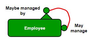
Let us suppose that we have an employee table. A manager supervises a subordinate. Every employee can have a supervisor except the CEO and there can be at most one boss for each employee. One employee may be the boss of more than one employee.
Let's suppose that REPORTS_TO is a recursive relationship on the Employee entity type where each Employee plays two roles.
- Supervisor
- Subordinate

Here, "Supervisor" and "Subordinate" are referred to as role names. The degree of the REPORTS_TO relationship is 1 (i.e., a unary relationship
- The minimum cardinality of the Supervisor role is 0 because the lowest-level employee (e.g., a subordinate) may not manage anyone.
- The maximum cardinality of the Supervisor role is N, as an employee can manage many subordinates.
For the Subordinate role:
- The minimum cardinality is 0, as the CEO, for example, is not a subordinate to anyone.
- The maximum cardinality is 1, as a subordinate can have only one manager.
Note: In this case, neither of the participants has total participation since the minimum cardinality for both roles is 0. Therefore, the relationship is represented with a single line (not a double line) in the ER diagram
Implementing a Recursive Relationship
To implement a recursive relationship, a foreign key of the employee’s manager number would be held in each employee record. A Sample table would look something like this:-
Emp_entity( Emp_no,Emp_Fname, Emp_Lname, Emp_DOB, Emp_NI_Number, Manager_no);

Manager no - (this is the employee no of the employee's manager)
Example:
CREATE TABLE employee (
    id INT PRIMARY KEY,
    name VARCHAR(50),
    manager_id INT,
    FOREIGN KEY (manager_id) REFERENCES employee(id)
);
Here, the employee table has a foreign key column called manager_id that references the id column of the same employee table. This allows you to create a recursive relationship where an employee can have a manager who is also an employee.
Sample Employee Table Structure:
| Emp_no | Emp_Fname | Emp_Lname | Emp_DOB | Emp_NI_Number | Manager_no |
|---|
| 1 | John | Doe | 1980-01-01 | 123456789 | NULL |
| 2 | Jane | Smith | 1990-05-15 | 987654321 | 1 |
| 3 | Bob | Johnson | 1985-03-22 | 112233445 | 1 |
In this table:
- Manager_no refers to the Emp_no of the employee’s manager.
- The CEO (employee 1 in this example) does not have a manager, hence their Manager_no is
NULL.
Similar Reads
Introduction of DBMS (Database Management System) A Database Management System (DBMS) is a software solution designed to efficiently manage, organize, and retrieve data in a structured manner. It serves as a critical component in modern computing, enabling organizations to store, manipulate, and secure their data effectively. From small application
8 min read
Need for DBMS A DBMS is essential for efficiently storing, organizing, and managing large amounts of data. It ensures data consistency, integrity, and security while allowing multiple users to access and manipulate data simultaneously. DBMS simplifies complex data operations and supports quick retrieval, making d
7 min read
Advantages of DBMS over File system File System: A File Management system is a DBMS that allows access to single files or tables at a time. In a File System, data is directly stored in a set of files. It contains flat files that have no relation to other files (when only one table is stored in a single file, then this file is known as
4 min read
Introduction of ER Model The Entity-Relationship Model (ER Model) is a conceptual model for designing a databases. This model represents the logical structure of a database, including entities, their attributes and relationships between them. Entity: An objects that is stored as data such as Student, Course or Company.Attri
10 min read
Recursive Relationships in ER diagrams A relationship between two entities of the same entity set is called a recursive relationship or repeated relationship. Here the same entity set participates more than once in a relationship type with a different role for each instance. Recursive relationships are often used to represent hierarchies
3 min read
Minimization of ER Diagrams Pre-Requisite: ER DiagramEntity-Relationship (ER) Diagram is a diagrammatic representation of data in databases, it shows how data is related to one another. In this article, we require previous knowledge of ER diagrams and how to draw ER diagrams.Minimization of ER Diagram simply means reducing the
4 min read
Enhanced ER Model As data complexity grows, the traditional ER model becomes less effective for database modeling. Enhanced ER diagrams extend the basic ER model to better represent complex applications. They support advanced concepts like subclasses, generalization, specialization, aggregation, and categories.ER mod
7 min read
Mapping from ER Model to Relational Model Converting an Entity-Relationship (ER) diagram to a Relational Model is a crucial step in database design. The ER model represents the conceptual structure of a database, while the Relational Model is a physical representation that can be directly implemented using a Relational Database Management S
7 min read
Relational Model in DBMS The Relational Model organizes data using tables (relations) consisting of rows and columns. Each column represents a specific attribute with a unique name, while each row holds data about a real-world entity or relationship. As a record-based model, it stores data in fixed-format records with defin
10 min read
Introduction of Relational Algebra in DBMS Relational Algebra is a formal language used to query and manipulate relational databases, consisting of a set of operations like selection, projection, union, and join. It provides a mathematical framework for querying databases, ensuring efficient data retrieval and manipulation. Relational algebr
9 min read